Posts

Practical Current Voltage Relationship
Image
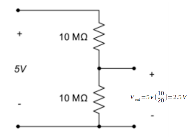
Practical Voltage and Current Measurement Prelab Lab     Lab Resistors Voltages Name MΩ Name V R1 2.2 Vs 4.99 R2 2.27 V out 2.28 Results              Non-Ideal Meter Rq(MΩ) Rm(MΩ) 1.85 10.03 Using this derived formula we can see that a 10.03 megaOhm resistor in parallel is the going to act as the resistance of the meter. 

Dusk Till Dawn Lab

Image
Dusk Till Dawn Objective Measurements Conclusion Objective         The objective of this lab is to use a transistor and a photocell to control an LED. In essence, we are making a night light.       Measurements Photoresistor Voltages Resistor(kΩ) Theory (V) Measured (V) % Difference 5.00 1.68 1.81 -6.99 20.00 3.35 1.94 72.68 7.00 2.08 1.94 7.07             Conclusion        There was a sizable discrepancy between the measured and calculated voltages at the 20k resistance. I am thinking this is probably because the resistor doesn't get anywhere to close to 20k. In fact, I added a projection for when the resistor is closer to 7k and the difference falls closer to 7%, similar to the 5k assumption from the first trial. I assume this tells that the photocell acutally has a much more narrow range of values than assumed. 

OP-Amp Labs

Image
Part 1: Inverting Amplifer Theory        The first lab with Op-Amps was to first get a very simple negative gain circuit working on a breadboard. In order to get a inverting gain we have to tie the positive terminal of the op-amp to the ground and drive power through the negative terminal. It is also required to tie feedback from the output to the negative input. Due to the large input resistance of the circuit there is practically no current running through those terminals, thus both positive and negative terminals are the same. When we have the positive to zero then we also have a zero voltage and the negative terminal.When you perform a nodal analysis of the negative input node then you can equate the current heading to the terminal as the current going through the feedback resistor. Experiment        We set up this circuit and applied the voltages to the terminals while we measured the v-out with a multi-meter.  Measurem...

Day one (Exploring the Breadboard)

Image
Exploring the Breadboard Objective Measurements Conclusion Objective         This was the first lab, as such it was relatively straight forward. I believe it was mostly for the purpose of making sure everyone sets up the blogger acount and invites the teacher. Measurements          First, two leads were placed on the the same row of a breadboard. A measurement of resistance was made; .4 ohms.         Next, two leads were placed between on separate rows. Once again, a measure of resistance was made. The reading was made; 1   .        Next, the jumper was moved to any random spot of the board, not in the same row. This reading was also a 1    .        Lastly, the same setup was made, with the addition a jumper between the two rows. Yet again, measurement were made.This time the reading was same as the reading on the...